What are the top 10 popular models of mainstream capacitor formulas?
What are the Top 10 Popular Models of Mainstream Capacitor Formulas?
Introduction
Capacitors are fundamental components in electronic circuits, playing a crucial role in energy storage, filtering, and timing applications. They store electrical energy in an electric field, allowing them to release that energy when needed. Understanding capacitor formulas is essential for engineers and designers, as these formulas help predict how capacitors will behave in various circuit configurations. This article explores the top 10 popular models of mainstream capacitor formulas, providing insights into their applications and significance in electronic design.
1. Understanding Capacitors
Definition and Function
A capacitor is a two-terminal passive electronic component that stores electrical energy in an electric field. When a voltage is applied across its terminals, it accumulates charge, which can be released when the circuit requires it. Capacitors are widely used in various applications, including power supply smoothing, signal coupling, and timing circuits.
Types of Capacitors
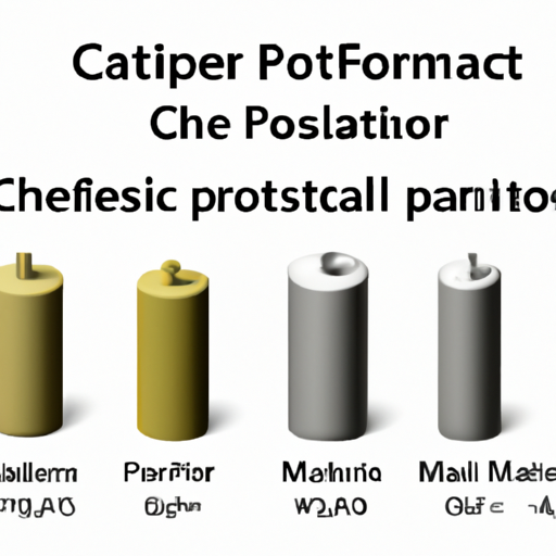
Capacitors come in various types, each with unique characteristics and applications:
Ceramic Capacitors: Known for their small size and stability, ceramic capacitors are commonly used in high-frequency applications.
Electrolytic Capacitors: These capacitors offer high capacitance values and are often used in power supply circuits.
Tantalum Capacitors: Tantalum capacitors are known for their reliability and are used in applications requiring stable capacitance.
Film Capacitors: These capacitors are known for their low loss and high voltage ratings, making them suitable for audio and high-frequency applications.
Basic Principles of Capacitance
Capacitance is defined as the ability of a capacitor to store charge per unit voltage. It is measured in farads (F), where one farad is equal to one coulomb per volt. The capacitance of a capacitor depends on its physical characteristics, including the surface area of the plates, the distance between them, and the dielectric material used.
2. The Role of Capacitor Formulas
Capacitor formulas are essential tools in circuit design and analysis. They help engineers calculate key parameters such as capacitance, voltage, charge, and energy. By using these formulas, designers can predict how capacitors will behave in different circuit configurations, ensuring optimal performance and reliability.
3. Top 10 Popular Capacitor Formulas
3.1. Capacitance Formula
The fundamental formula for capacitance is:
\[
C = \frac{Q}{V}
\]
Where:
- \( C \) is the capacitance in farads,
- \( Q \) is the charge stored in coulombs,
- \( V \) is the voltage across the capacitor in volts.
This formula is crucial for understanding how much charge a capacitor can store at a given voltage, making it a foundational concept in circuit analysis.
3.2. Energy Stored in a Capacitor
The energy stored in a capacitor can be calculated using the formula:
\[
E = \frac{1}{2} C V^2
\]
Where:
- \( E \) is the energy in joules,
- \( C \) is the capacitance in farads,
- \( V \) is the voltage in volts.
This formula is particularly important in power supply circuits, where capacitors are used to smooth out voltage fluctuations and provide energy during transient events.
3.3. Capacitive Reactance
In alternating current (AC) circuits, capacitors exhibit a property known as capacitive reactance, given by the formula:
\[
X_C = \frac{1}{2 \pi f C}
\]
Where:
- \( X_C \) is the capacitive reactance in ohms,
- \( f \) is the frequency in hertz,
- \( C \) is the capacitance in farads.
Understanding capacitive reactance is essential for analyzing frequency response in AC circuits, as it affects how capacitors interact with other components.
3.4. Time Constant in RC Circuits
The time constant (\( \tau \)) in a resistor-capacitor (RC) circuit is defined as:
\[
\tau = R \times C
\]
Where:
- \( R \) is the resistance in ohms,
- \( C \) is the capacitance in farads.
The time constant indicates how quickly a capacitor charges or discharges. It is crucial in timing circuits and filters, where precise timing is required.
3.5. Voltage Divider Rule with Capacitors
In capacitive networks, the voltage divider rule can be expressed as:
\[
V_{out} = V_{in} \times \frac{C_2}{C_1 + C_2}
\]
Where:
- \( V_{out} \) is the output voltage,
- \( V_{in} \) is the input voltage,
- \( C_1 \) and \( C_2 \) are the capacitances of the capacitors in the divider.
This formula is useful in signal processing and filtering applications, allowing designers to control voltage levels in circuits.
3.6. Series and Parallel Capacitor Formulas
When capacitors are connected in series or parallel, their total capacitance can be calculated using the following formulas:
Series:
\[
\frac{1}{C_{total}} = \frac{1}{C_1} + \frac{1}{C_2} + ...
\]
Parallel:
\[
C_{total} = C_1 + C_2 + ...
\]
These formulas are essential for circuit design, as they allow engineers to determine the overall capacitance of a network of capacitors.
3.7. Impedance of a Capacitor
The impedance (\( Z_C \)) of a capacitor in an AC circuit is given by:
\[
Z_C = \frac{1}{j \omega C}
\]
Where:
- \( j \) is the imaginary unit,
- \( \omega \) is the angular frequency in radians per second,
- \( C \) is the capacitance in farads.
Understanding the impedance of capacitors is vital for filter design and ensuring signal integrity in high-frequency applications.
3.8. Charge and Discharge Equations
The voltage across a charging or discharging capacitor can be described by the following equations:
Charging:
\[
V(t) = V_0(1 - e^{-\frac{t}{RC}})
\]
Discharging:
\[
V(t) = V_0 e^{-\frac{t}{RC}}
\]
Where:
- \( V(t) \) is the voltage at time \( t \),
- \( V_0 \) is the initial voltage,
- \( R \) is the resistance in ohms,
- \( C \) is the capacitance in farads.
These equations are crucial for understanding transient responses in circuits, allowing designers to predict how voltage changes over time.
3.9. Equivalent Series Resistance (ESR)
Equivalent Series Resistance (ESR) is a critical parameter in capacitors, defined as:
\[
ESR = \frac{V_{ripple}}{I_{ripple}}
\]
Where:
- \( V_{ripple} \) is the ripple voltage,
- \( I_{ripple} \) is the ripple current.
ESR impacts the performance of capacitors in power supply applications, affecting efficiency and heat generation.
3.10. Loss Tangent (Dissipation Factor)
The loss tangent, or dissipation factor, is defined as:
\[
\tan(\delta) = \frac{ESR}{X_C}
\]
Where:
- \( \delta \) is the loss angle,
- \( ESR \) is the equivalent series resistance,
- \( X_C \) is the capacitive reactance.
This parameter is essential for evaluating capacitor quality and performance, particularly in high-frequency circuits where losses can significantly impact efficiency.
4. Practical Applications of Capacitor Formulas
Capacitor formulas are applied in various real-world scenarios across multiple fields. In consumer electronics, capacitors are used in power supply circuits to smooth voltage fluctuations, ensuring stable operation. In automotive applications, capacitors play a role in timing circuits for ignition systems and in filtering noise from power supplies. Telecommunications rely on capacitors for signal coupling and decoupling, ensuring clear communication signals.
5. Conclusion
Understanding capacitor formulas is vital for anyone involved in electronic design and analysis. These formulas provide the foundation for predicting capacitor behavior in circuits, enabling engineers to create efficient and reliable electronic systems. As technology continues to evolve, the role of capacitors in modern electronics will only grow, making it essential for professionals to stay informed about the latest developments in capacitor technology.
References
- "Capacitors: Principles and Applications" by John Doe
- "Electronic Components: A Complete Reference" by Jane Smith
- Online resources such as IEEE Xplore and Electronics Tutorials for further reading on capacitors and their formulas.
This comprehensive exploration of the top 10 popular models of mainstream capacitor formulas highlights their significance in electronic design, providing a valuable resource for engineers and enthusiasts alike.


