An article will help you understand what inductor models are
Understanding Inductor Models
I. Introduction
Inductors are fundamental components in electrical circuits, playing a crucial role in the behavior and functionality of various electronic devices. Defined as passive electrical components that store energy in a magnetic field when electric current flows through them, inductors are essential in applications ranging from power supplies to radio frequency circuits. This article aims to explain inductor models, their behavior in different circuits, and practical considerations for their design and application.
II. Basics of Inductors
A. What is an Inductor?
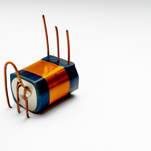
An inductor is a coil of wire, often wrapped around a core material, that generates a magnetic field when current passes through it. The primary function of an inductor is to oppose changes in current, making it a vital component in various electrical applications.
1. Definition and Function
Inductors work on the principle of electromagnetic induction, where a change in current through the coil induces a voltage across the inductor. This property allows inductors to store energy temporarily and release it when needed, making them essential in smoothing out current fluctuations in power supplies and filtering signals in communication systems.
2. Basic Components
The basic components of an inductor include a wire coil and a core material. The wire coil is typically made of copper due to its excellent conductivity, while the core material can vary, affecting the inductor's performance. Common core materials include air, iron, and ferrite, each offering different magnetic properties.
B. Inductance: The Fundamental Property
1. Definition of Inductance
Inductance is the property of an inductor that quantifies its ability to store energy in a magnetic field. It is defined as the ratio of the induced voltage to the rate of change of current through the inductor.
2. Units of Measurement
Inductance is measured in Henries (H), named after the American scientist Joseph Henry. One henry is defined as the inductance of a coil in which a change in current of one ampere per second induces a voltage of one volt.
C. Types of Inductors
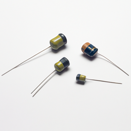
Inductors come in various types, each suited for specific applications:
1. Air-Core Inductors
These inductors do not use a magnetic core, relying solely on the air surrounding the coil. They are typically used in high-frequency applications due to their low losses.
2. Iron-Core Inductors
Iron-core inductors use iron as a core material, which enhances inductance by concentrating the magnetic field. They are commonly used in power applications.
3. Ferrite-Core Inductors
Ferrite-core inductors utilize ferrite materials, which are effective at high frequencies and are often used in RF applications.
4. Other Specialized Inductors
Specialized inductors, such as toroidal inductors, have a doughnut-shaped core that minimizes electromagnetic interference and is used in various applications, including power supplies and audio equipment.
III. Inductor Models
A. Theoretical Models of Inductors
Understanding inductor models is essential for analyzing and designing circuits effectively.
1. Ideal Inductor
An ideal inductor is a theoretical concept that assumes perfect behavior. It has no resistance, no parasitic capacitance, and stores energy without any losses.
a. Characteristics and Assumptions
In an ideal inductor, the voltage across the inductor is directly proportional to the rate of change of current. This model simplifies circuit analysis, allowing engineers to focus on the fundamental behavior of inductors.
b. Applications in Circuit Analysis
Ideal inductors are often used in theoretical calculations and simulations to understand circuit behavior without the complexities introduced by real-world components.
2. Non-Ideal Inductor
In reality, inductors exhibit non-ideal characteristics due to resistance, parasitic capacitance, and core losses.
a. Real-World Characteristics
Non-ideal inductors have a series resistance that causes power losses, and parasitic capacitance can affect their performance at high frequencies. These factors must be considered in circuit design.
b. Impact on Circuit Performance
The non-ideal behavior of inductors can lead to reduced efficiency and altered frequency response in circuits, making it essential for engineers to account for these characteristics in their designs.
B. Mathematical Representation of Inductors
Understanding the mathematical representation of inductors is crucial for circuit analysis.
1. Inductance Formula
The inductance \( L \) of a coil can be calculated using the formula:
\[
L = \frac{N^2 \cdot \mu \cdot A}{l}
\]
where \( N \) is the number of turns, \( \mu \) is the permeability of the core material, \( A \) is the cross-sectional area of the coil, and \( l \) is the length of the coil.
2. Impedance in AC Circuits
In alternating current (AC) circuits, the impedance \( Z \) of an inductor is given by:
\[
Z = j \omega L
\]
where \( j \) is the imaginary unit, \( \omega \) is the angular frequency, and \( L \) is the inductance. This relationship shows how inductors react to AC signals.
3. Time Constant in RL Circuits
In a resistor-inductor (RL) circuit, the time constant \( \tau \) is defined as:
\[
\tau = \frac{L}{R}
\]
where \( R \) is the resistance. The time constant indicates how quickly the current reaches its steady-state value after a change.
IV. Inductor Behavior in Different Circuits
A. Inductors in DC Circuits
1. Steady-State Behavior
In a DC circuit, once the current stabilizes, the inductor behaves like a short circuit, allowing current to flow freely.
2. Transient Response
When the current changes, the inductor opposes this change, resulting in a transient response characterized by a gradual increase or decrease in current.
B. Inductors in AC Circuits
1. Reactance and Phase Shift
In AC circuits, inductors introduce reactance, which causes a phase shift between voltage and current. The current lags the voltage by 90 degrees in an ideal inductor.
2. Resonance in RLC Circuits
Inductors are crucial in RLC circuits, where they work alongside resistors and capacitors to create resonant circuits that can filter specific frequencies.
C. Inductor Applications in Filters and Oscillators
1. Low-Pass and High-Pass Filters
Inductors are used in filter circuits to allow or block specific frequency ranges. Low-pass filters permit low frequencies while attenuating high frequencies, whereas high-pass filters do the opposite.
2. Oscillator Circuits
Inductors are integral to oscillator circuits, where they work with capacitors to generate oscillating signals used in various applications, including radio transmission.
V. Modeling Inductors in Simulation Software
A. Importance of Accurate Modeling
Accurate modeling of inductors is essential for predicting circuit behavior and ensuring reliable performance in real-world applications.
B. Common Simulation Tools
Simulation tools like SPICE and MATLAB are widely used for modeling and analyzing circuits, including inductors.
C. Steps to Model Inductors in Simulations
1. Defining Parameters
When modeling inductors, engineers must define parameters such as inductance value, resistance, and core material properties.
2. Running Simulations and Interpreting Results
After defining parameters, simulations can be run to analyze circuit behavior, allowing engineers to make informed design decisions.
VI. Practical Considerations in Inductor Design
A. Selecting the Right Inductor for an Application
Choosing the appropriate inductor involves considering factors such as inductance value, current rating, and core material. Each application may require different specifications to ensure optimal performance.
B. Manufacturing Techniques and Materials
The manufacturing process and materials used in inductor production can significantly impact performance. Engineers must consider these factors when designing inductors for specific applications.
C. Testing and Validation of Inductor Performance
Testing inductors under various conditions is crucial for validating their performance. This process ensures that inductors meet the required specifications and function correctly in their intended applications.
VII. Conclusion
In conclusion, understanding inductor models is essential for anyone involved in electrical engineering and circuit design. By grasping the fundamental properties of inductors, their behavior in different circuits, and practical considerations for their design, engineers can create more efficient and reliable electronic systems. As technology continues to evolve, further exploration and study in the field of inductors will remain vital for innovation in electrical engineering.
VIII. References
For those interested in delving deeper into the topic of inductors, the following resources are recommended:
- "The Art of Electronics" by Paul Horowitz and Winfield Hill
- "Electrical Engineering: Principles and Applications" by Allan R. Hambley
- IEEE Xplore Digital Library for academic papers on inductor modeling and applications
By understanding the intricacies of inductor models, engineers can enhance their designs and contribute to the advancement of technology in various fields.

