How to choose the spot capacitor wiring diagram?
How to Choose the Spot Capacitor Wiring Diagram
I. Introduction
In the world of electronics, capacitors play a crucial role in various applications, from power supply filtering to signal coupling. Among the different types of capacitors, spot capacitors are particularly significant due to their specific applications in circuits. Understanding how to choose the right wiring diagram for these components is essential for ensuring optimal performance and safety. This article aims to guide you through the process of selecting the appropriate spot capacitor wiring diagram, highlighting key considerations and best practices.
II. Understanding Spot Capacitors
A. What are Spot Capacitors?
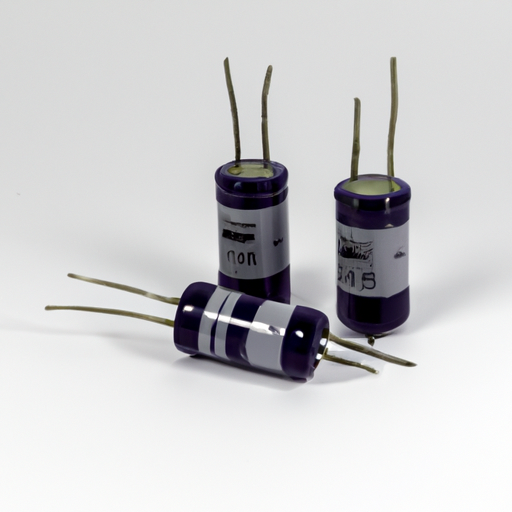
Spot capacitors are specialized capacitors designed for specific applications, often found in electronic circuits where precise capacitance is required. They serve various functions, including energy storage, voltage smoothing, and signal filtering. Spot capacitors can be categorized into several types, including:
1. **Electrolytic Capacitors**: Known for their high capacitance values, these capacitors are polarized and typically used in power supply applications.
2. **Ceramic Capacitors**: These non-polarized capacitors are often used in high-frequency applications due to their stability and low losses.
3. **Film Capacitors**: Known for their reliability and low self-inductance, film capacitors are commonly used in audio and RF applications.
B. Key Specifications to Consider
When selecting a spot capacitor, several key specifications must be taken into account:
1. **Capacitance Value**: This is the measure of a capacitor's ability to store charge, typically expressed in microfarads (µF) or picofarads (pF).
2. **Voltage Rating**: The maximum voltage a capacitor can handle without failing. It is crucial to choose a capacitor with a voltage rating higher than the maximum voltage in the circuit.
3. **Tolerance**: This indicates how much the actual capacitance can vary from the stated value, usually expressed as a percentage.
4. **Temperature Coefficient**: This specification describes how the capacitance value changes with temperature, which can affect performance in varying environmental conditions.
III. Importance of Wiring Diagrams
A. Role of Wiring Diagrams in Electrical Systems
Wiring diagrams are essential tools in electrical engineering, providing a visual representation of how components are connected within a circuit. They serve as a roadmap for installation, maintenance, and troubleshooting.
B. Benefits of Using a Wiring Diagram for Spot Capacitors
1. **Ensures Correct Connections**: A wiring diagram helps ensure that all connections are made correctly, reducing the risk of errors during installation.
2. **Prevents Electrical Faults**: By following a wiring diagram, you can avoid common pitfalls that lead to short circuits or component damage.
3. **Facilitates Troubleshooting**: In the event of a malfunction, a wiring diagram can help identify the source of the problem quickly.
IV. Factors to Consider When Choosing a Wiring Diagram
A. Application Requirements
When selecting a wiring diagram, consider the specific requirements of your application:
1. **Load Characteristics**: Understand the load that the capacitor will be supporting, as this will influence the choice of wiring configuration.
2. **Circuit Configuration**: The overall design of the circuit will dictate how the capacitor should be wired, whether in series or parallel.
B. Type of Capacitor
The type of capacitor you are using will also affect the wiring diagram:
1. **Electrolytic Capacitors**: These require careful attention to polarity in the wiring diagram.
2. **Ceramic and Film Capacitors**: These are generally non-polarized, allowing for more flexibility in wiring.
C. Safety Standards and Regulations
1. **Compliance with Local Codes**: Ensure that your wiring diagram adheres to local electrical codes and standards.
2. **Manufacturer Guidelines**: Always refer to the manufacturer's specifications and recommendations for wiring to ensure safety and reliability.
V. Common Wiring Diagrams for Spot Capacitors
A. Series vs. Parallel Configurations
When wiring spot capacitors, you can choose between series and parallel configurations, each with its advantages and disadvantages:
1. **Series Configuration**: In this setup, capacitors are connected end-to-end. The total capacitance is reduced, but the voltage rating increases. This configuration is useful when higher voltage handling is required.
- **Advantages**: Higher voltage rating, reduced capacitance.
- **Disadvantages**: Total capacitance decreases, which may not be suitable for all applications.
2. **Parallel Configuration**: Here, capacitors are connected alongside each other. The total capacitance increases, while the voltage rating remains the same.
- **Advantages**: Increased total capacitance, suitable for energy storage.
- **Disadvantages**: Voltage rating is limited to the lowest-rated capacitor in the group.
B. Typical Wiring Diagrams
1. **Basic Wiring Diagram Example**: A simple diagram showing a single capacitor connected to a power source and load.
2. **Complex Wiring Diagram Example**: A more intricate diagram illustrating multiple capacitors in series and parallel configurations, along with other circuit components.
C. Visual Aids and Resources for Reference
Utilizing visual aids, such as diagrams and charts, can greatly enhance your understanding of wiring configurations. Online resources, textbooks, and manufacturer documentation can provide valuable insights.
VI. Best Practices for Wiring Spot Capacitors
A. Proper Installation Techniques
1. **Tools and Materials Needed**: Gather all necessary tools, including wire strippers, soldering iron, and multimeter, before starting the installation.
2. **Step-by-Step Installation Guide**:
- Review the wiring diagram thoroughly.
- Prepare the capacitor leads by stripping the insulation.
- Connect the capacitor according to the diagram, ensuring correct polarity for electrolytic capacitors.
- Secure all connections and double-check for accuracy.
B. Maintenance and Inspection Tips
1. **Regular Checks for Wear and Tear**: Periodically inspect capacitors for signs of damage, such as bulging or leakage.
2. **Signs of Failure to Watch For**: Be aware of symptoms like unusual noises, overheating, or circuit malfunctions, which may indicate capacitor failure.
VII. Troubleshooting Common Issues
A. Identifying Wiring Problems
1. **Symptoms of Incorrect Wiring**: Look for signs such as circuit failure, unexpected behavior, or blown fuses.
2. **Diagnostic Steps to Take**: Use a multimeter to check for continuity and voltage levels, and compare with the wiring diagram.
B. Solutions to Common Wiring Issues
1. **Rewiring Techniques**: If incorrect wiring is identified, carefully follow the wiring diagram to re-establish proper connections.
2. **Replacement Options**: If a capacitor is found to be faulty, replace it with a new one that meets the required specifications.
VIII. Conclusion
Choosing the right wiring diagram for spot capacitors is crucial for ensuring the reliability and safety of electrical systems. By understanding the specifications of spot capacitors, the importance of wiring diagrams, and the factors to consider during selection, you can make informed decisions that enhance performance. When in doubt, consulting with professionals can provide additional guidance and ensure compliance with safety standards. Spot capacitors play a vital role in electrical systems, and proper wiring is key to their effective operation.
IX. References
- Suggested readings and resources for further learning about capacitors and wiring diagrams.
- Industry standards and guidelines for capacitor wiring, including local electrical codes and manufacturer recommendations.
By following the insights provided in this article, you can confidently choose the right wiring diagram for your spot capacitors, ensuring optimal performance and safety in your electrical applications.

